
↓Wear-resistant spiral elbow
- →Wear problems in pneumatic transport piping
- →Wear-Resistant Helical Elbow: Solving Core Industrial Conveying Challenges Based on Fluid Mechanics
- →Spiral elbow principle
- →Technical Analysis of the Spiral Wear-Resistant Elbow
- →The appeal of wear-resistant spiral elbows
- →Engineering Theory and Application Principles of the Wear-Resistant Spiral Elbow
- →Research on simplified calculation method for pneumatic transportation
- →Spiral wear-resistant elbows solve common problems
- →Ceramic Wear-Resistant Spiral Elbow
- →Why Can M Battery Factory Avoid the Spontaneous Combustion Trap
- → Specifications of wear-resistant spiral elbows
Study on the Simple Calculation Method of Pneumatic Conveying
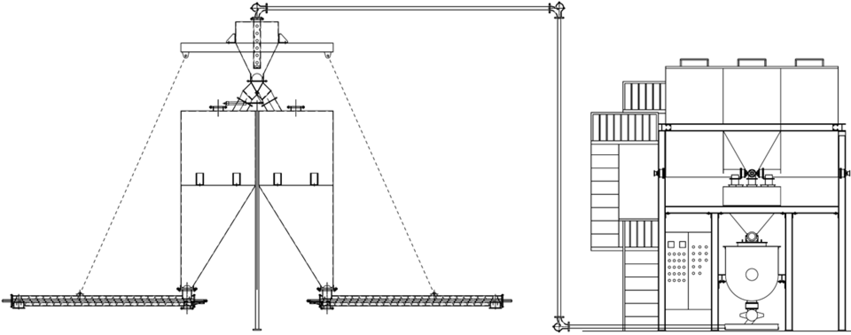
System Specifications:
- Conveyed Material: X fine powder
- Bulk Density of Conveyed Material: 0.55 × Particle Diameter 0.12mm
- Air Piping from Blower to Rotary Feeder Device (Clean Air):
- Straight Pipe: 60 meters
- Elbows: 8 locations
- From Rotary Feeder Device to Distributor:
- Horizontal Conveying Distance: Lh = 60M
- Vertical Conveying Distance: Lv = 33M
- 90-degree Elbows: 7 locations
- 45-degree Elbows: 1 location
- Branch Pipes for Conveyed Material: 5 locations
- Conveying Capacity of Material: Ws = 10,000Kg/Hr
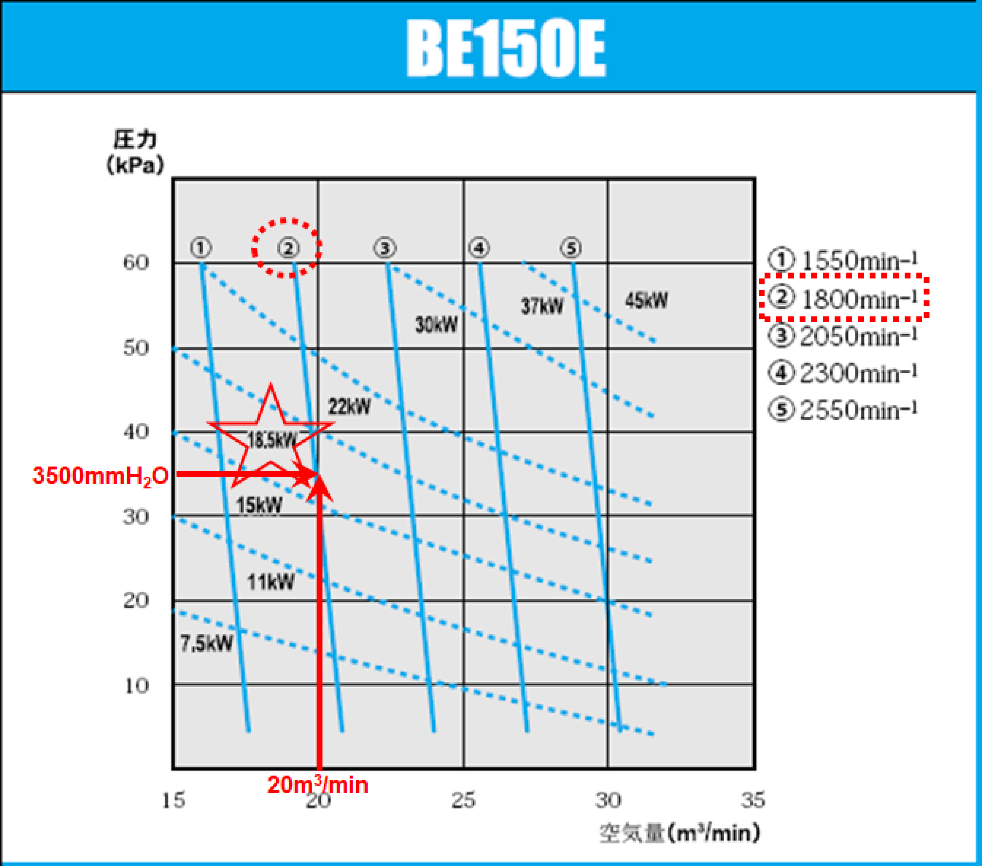
- Airflow for Conveying (Wa): (Qa) = 13.
- Current Blower Capacity: 20M3/min
- Specific Weight of Air (λa): 1.2Kg/M3
- Conveying Air Velocity (Va): 16–24M/S ≒ 20M/S (Reference: “Powder and Granular Material Transport Technology,” Nikkan Kogyo Shimbun, Pipeline Transport Equipment, Page 240)
- Mixture Ratio (μs): (Γ) = 10,000 ÷ 60 ÷ 1.2 ÷ 20 ≒ 7 (Reference: “Powder and Granular Material Transport, Storage and Supply,” Chemical Industry Publishing, Air Transport Machine Design Guidelines, Page 39)
- Conveying Method: Blow-type
- Inner Diameter of Conveying Pipe (ϕDa): √(4Qa ÷ 60πVa) = 0.146M ≒ 151mm (6-inch SCH40 Pipe) (Reference: “Powder and Granular Material Transport Technology,” Nikkan Kogyo Shimbun, Pipeline Transport Equipment, Page 241)
- Conveying Air Velocity (M/s): Approx. 20M/S
- Material Supply Method: Intermittent Supply by Rotary Feeder (Airlock)
- Pressure Loss (ΔP):P=Pair+Pac+Pm+Psep+Pex+Pb
- ΔPair: Pressure loss in air piping from blower outlet to rotary feeder device
- ΔPac: Acceleration loss
- ΔPm: Pressure loss in conveying pipe
- ΔPsep: Pressure loss in bag filter (not considered as it is a blow system)
- ΔPex: Pressure loss in cyclone dust collector (not considered as it is a blow system)
- ΔPb: Exhaust loss (pressure loss from bag filter to auxiliary fan)
Simple Calculation Results:
- Q = 60VaπD² ÷ 4 = 20.0898567 M3/min ≒ 20M3/min
- ΔP = (1.2 × 0.025 × 20² × 99) ÷ (2 × 9.80665 × 0.151) ≒ 410mmaq
- For a mixture ratio of 7, 410 × 7 = 2870mmaq
- Considering a 15–20% increase in pressure loss based on experience:
- 2870 × 1.2 = 3444mmaq → Sufficient for transport.
- Blower Power Calculation:
- 20 × 3500 ÷ 6120 ÷ 0.6 ÷ 0.74 ≒ 25.8Hp
- Can be operated with 25Hp to 30Hp.
Relationship Diagrams:
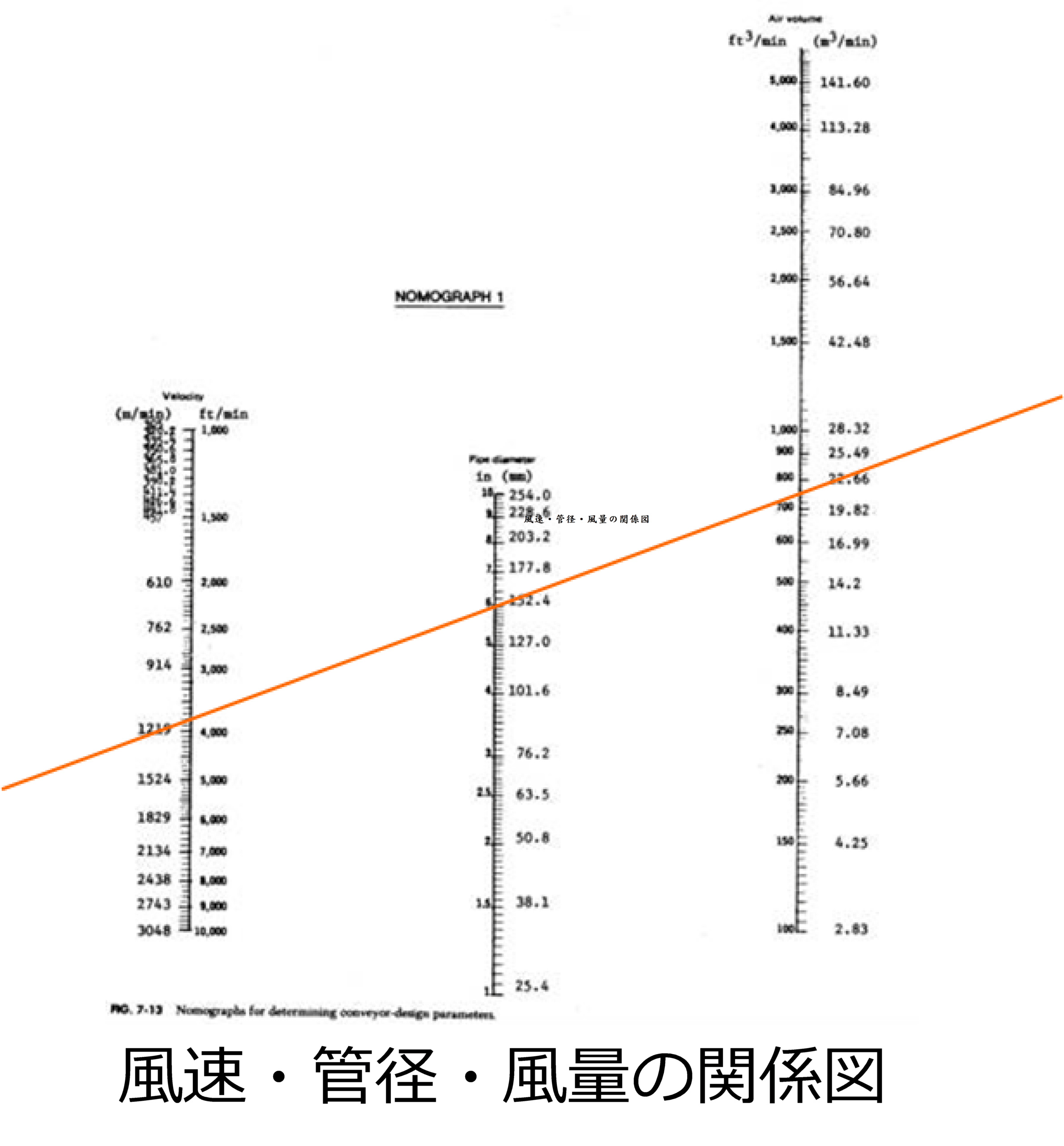 Airflow, Pipe Diameter, and Air Velocity
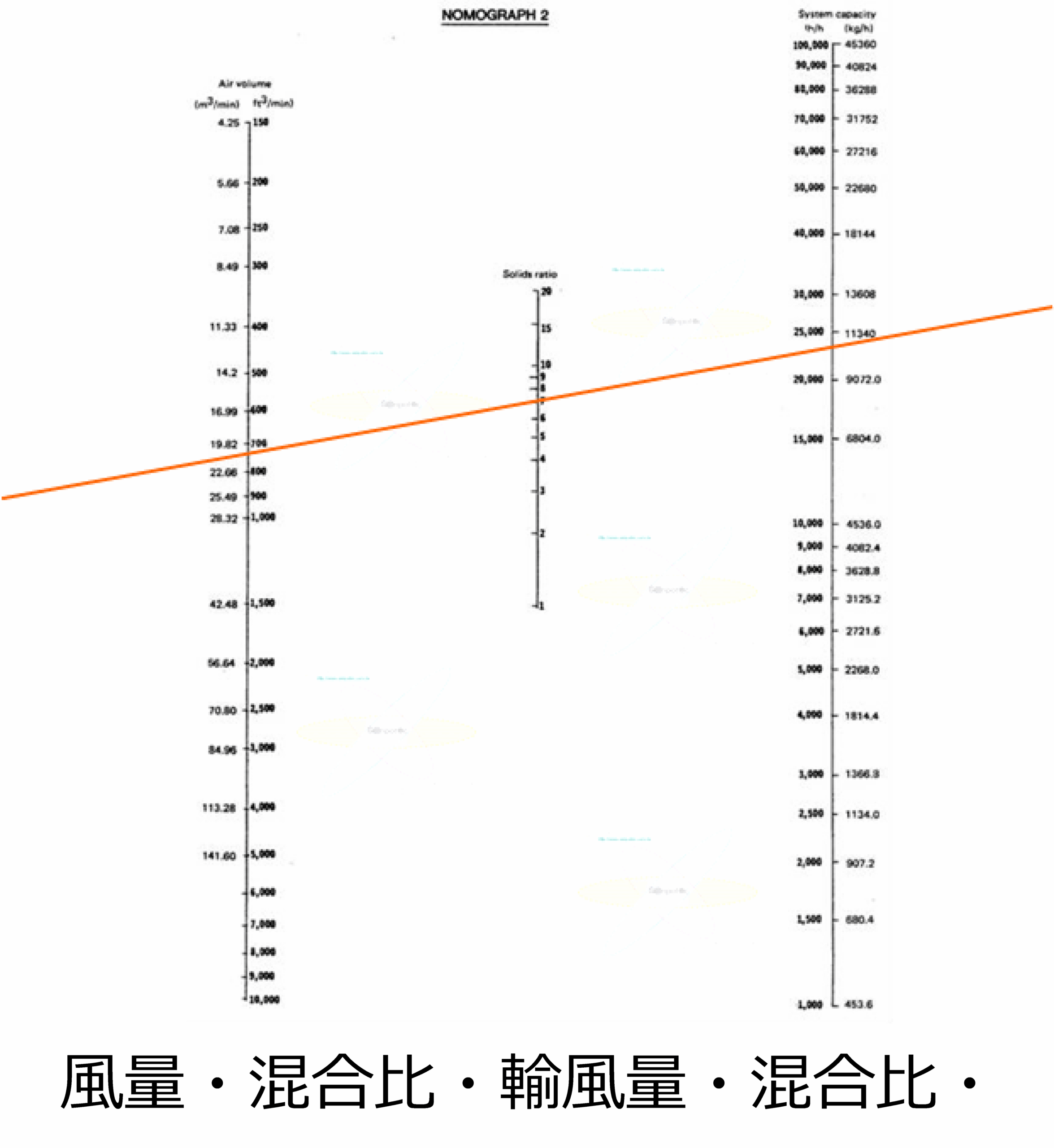 Airflow, Mixture Ratio, and Conveying Capacity
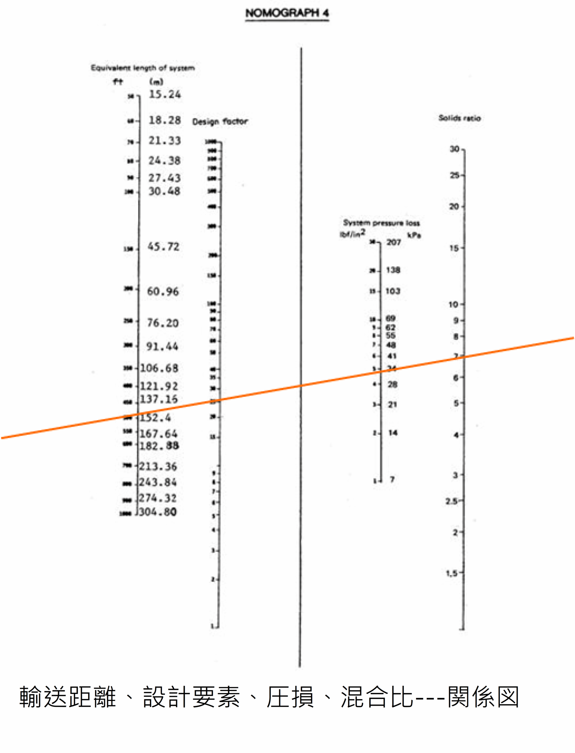 Conveying Distance, Design Factors, Pressure Loss, and Mixture Ratio
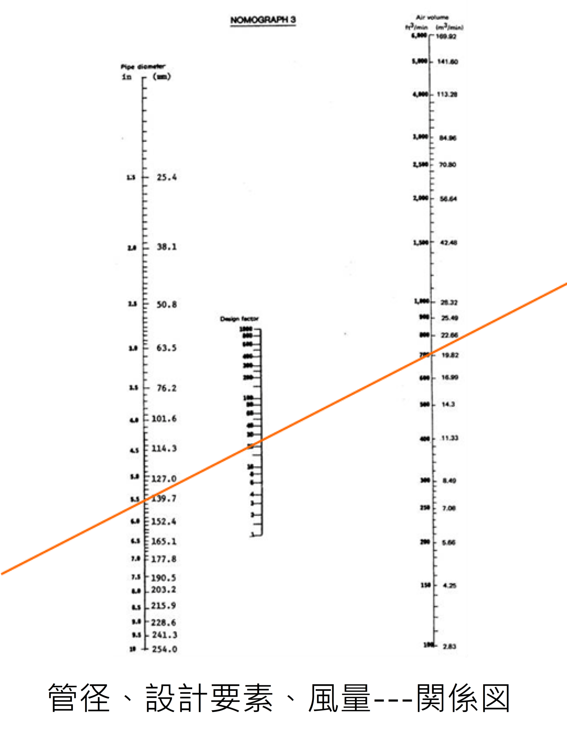 Pipe Diameter, Design Factors, and Airflow
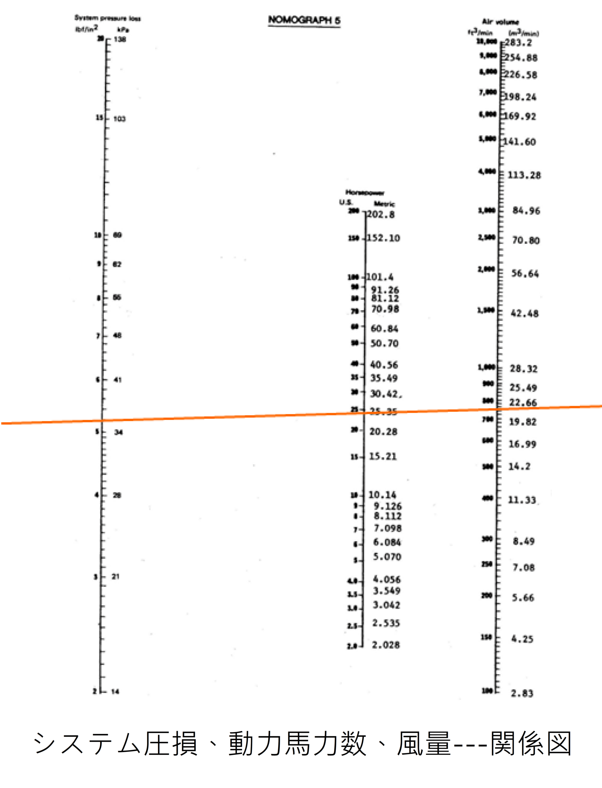 System Pressure Loss, Power Requirements, and Airflow
Is Pressure Loss Lower than That of Standard Elbows?
Typically, SCH40 seamless steel pipes are used in pneumatic conveying systems, and the design parameters are based on this standard.
Reference Inner Pipe Diameters:
- 4” — 102.3mm
- 5” — 126.6mm
- 6” — 151mm
- 8” — 199.9mm
- 10” — 248.8mm
- 12” — 297.9mm
- 14” — 333.4mm
- 16” — 381mm
The pressure loss coefficient (ζsb) is relatively related to the curvature radius (ρ) and the inner diameter (D). Standard values based on reference materials are as follows:
| Curvature Radius/Pipe Shape | Pressure Loss Coefficient |
| ρ/D | ζsb |
| 2 | 1.5 |
| 4 | 0.75 |
| 6 | 0.5 |
| 17 | 0.38 |
Pressure Loss Coefficient (ζsb) for 20R Long Elbows:
- A 20R long elbow typically has a pressure loss coefficient of around 0.50, which includes the pressure loss due to the curvature radius in the standard straight pipe.
- Below is a comparison of the pressure loss differences between a 20R long elbow and a spiral wear-resistant elbow.
Verification Example:
- For a 4-inch 20R long elbow:
- Set air velocity V = 20M/S and mixture ratio η = 1
- Curvature radius: 102.3 ÷ 2 × 20 = 1023mm
- Flow distance: 2 × 10²³ × π ÷ 4 = 1607mm
- ζsb ≈ 0.40 (based on reference data)
- Pressure Loss Calculation for a 4” 20R Long Elbow:
- ΔPn = (1.2 × 0.025 × 20² × 1.607) ÷ (2 × 9.80665 × 0.1023) = 9.6110mmaq
- ΔP206 = 9.6110 × (1 + 0.40) = 13.4555mmaq
- Similarly, for a 6” elbow:
- ΔP206 = {(1.2 × 0.025 × 20² × 2.372) ÷ (2 × 9.80665 × 0.151)} × (1 + 0.40) = 13.4554mmaq
Pressure Loss Calculation for Spiral Wear-Resistant Elbows:
- Reference Inner Pipe Diameters:
- 4” — 104.5mm
- 5” — 129.66mm
- 6” — 154.2mm
- 8” — 203.5mm
- 10” — 254.6mm
- 12” — 305.7mm
- 14” — 339.8mm
- 16” — 390.6mm
The flow distance of the spiral wear-resistant elbow is used to compare pressure loss differences.
4″ Elbow:
375 + 328 + 228 = 931mm ζsb = 931 / 104.5 = 8.91 According to reference materials, the pressure loss coefficient is below 0.50.
∵ The spiral pressurization (low pressure loss) of the spiral wear-resistant elbow reduces the coefficient to 1/√2 of its original value as it passes through the 45° spiral angle.
6″ Elbow:
465 + 484 + 292 = 1241mm ζsb = 1241 / 154.2 = 8.05 According to reference materials, the pressure loss coefficient is below 0.50.
When calculating the spiral wear-resistant elbow at 20M/S:
For the 4-inch spiral wear-resistant elbow, the internal chamber passage distance is 931mm.
4″ Spiral Wear-Resistant Elbow Pressure Loss Calculation: ΔPn = (1.2 × 0.025 × 20² × 0.931) / (2 × 9.80665 × 0.1045) = 5.451mmaq ΔPse = {(5.451 × (1 + 0.5))} / √2 = 5.7817mmaq
For the 6″ spiral elbow, the flow distance is 1241mm.
Using a similar calculation: ΔPn = (1.2 × 0.025 × 20² × 1.241) / (2 × 9.80665 × 0.1542) = 4.924mmaq ΔPse = {(4.924 × (1 + 0.5))} / √2 = 5.223mmaq